LTSpice based simulations of two mutually delay-coupled digital phase-locked loops (DPLLs). These simulations take into account the dynamics of the voltages and currents, as well as the processing time of different electronic circuitry used in PLL components. We compare the results to our theoretical predictions from the phase-model.
We use LTSpice, an open source analog circuit simulator to simulate systems of coupled DPLL on the level of the voltage and current time-series.
Using this industry-standard approach to test the circuit architectures down to the transistor level before setting up the prototype systems for experimentation allows to identify potential problems such as parasitic resistances and capacitances. We also use it to gain a better intuition on the dynamics within the circuitry as components become heterogeneous and are subject to noise.
Here we present our current ongoing work on a system of two mutually delay-coupled digital phase-locked loops (DPLLs), each consisting of a phase detector (XOR or flip-flop), a loop filter (first order low pass filter) and an voltage-controlled oscillator (VCO). The VCO is a ring oscillator which is set up from a closed chain of inverter elements, designed by Jacob Baker and available from YOUSPICE.
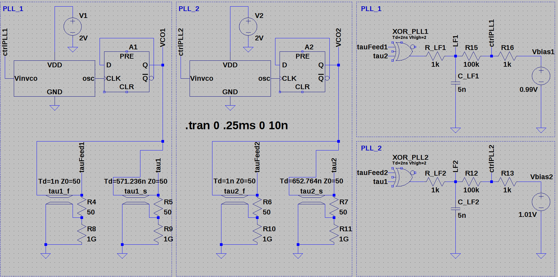
Fig.1: Two digital phase-locked loops with first order loop filter, delayed feedback and transmission lines for mutual coupling. The DPLLs are separated into two part, the VCO and delay-lines (left), and the phase-detector and loop filter components (right). No reference clock involved.
Before going into the details of this circuit, we show the response curve of the VCO plotted against the input voltage at Vinvco.The VCO is supplied by a 2V power source and we changed the parasitic capacitor in the inverter subcircuits of the VCO to fF.
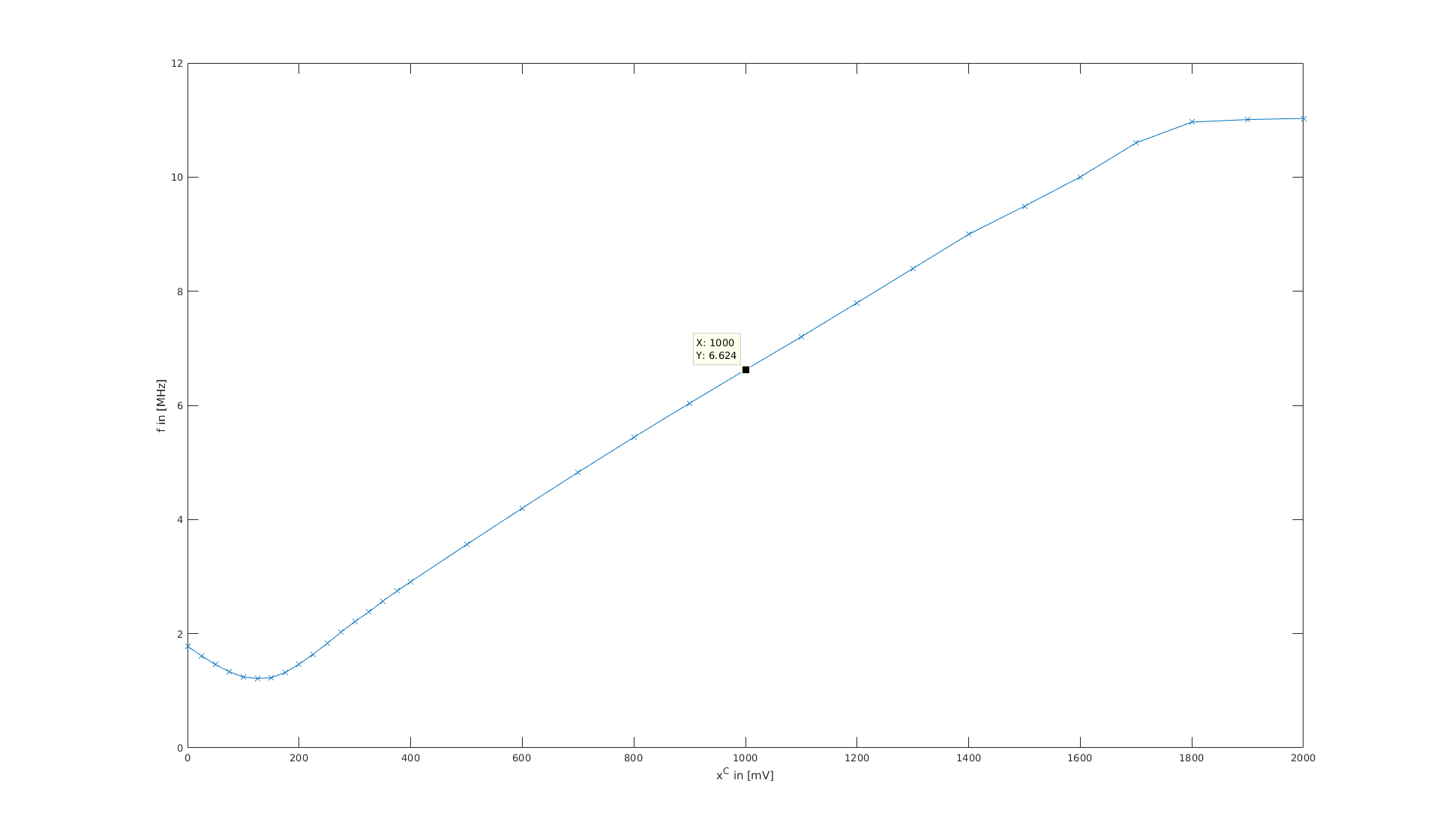
Fig. 2: VCO with rectangular output signals designed by R. Jacob Baker. The measurements are included as a table.Fig. 3: Response curve of VCO (ring oscillator) for supply voltage 2V and parasitic capacitance .
Self-organized synchronization in electronic systems
[collaborators: Nirmal Punetha, Niko Joram, Suropriya Saha, Shamik Gupta, Sara Ameli Kalkouran, Josefine Asmus, Daniel Platz, Benjamin Friedrich, David J. Jörg, Alexandros Pollakis, Wolfgang Rave, Gerhard Fettweis, Frank Ellinger, Frank Jülicher]
This project started as a collaboration between the Max-Planck Institute for the Physics of Complex Systems and the Vodafone Chair Mobile Communications Systems at the TU-Dresden within the Center for Advancing Electronic Dresden. In this project we explore self-organized synchronization of mutually delay-coupled electronic clocks. This concept with a flat hierarchy is different from the State-of-the-Art hierarchical approach to synchronization, where a reference clock dictates the time to all other clocks.
In electronic systems, information processing shared between large numbers of units and in parallel has become more and more important. Prominent examples are antenna arrays in radar and mobile communications, servers and databases, networks-on-chip, indoor and global navigation solutions, swarms of drones and robots, and sensor arrays. In such systems, robust operation and processing requires coordination of the components involved. This can be achieved by a common time-reference that is provided by clocking devices. In practice it can be a challenging task to provide such a system-wide reference, given the heterogeneity of CMOS integrated circuitry, the dimensions in space or number of such systems and the frequencies of operation. The time-delays in electronic signal transmission become important when the wavelength of a signal is of the order of the spatial dimension of the system. That means, that signal transmission delays become relevant once they are of the order of the time-scales of operation of the system. For example, for electronic components that are clocked at frequencies in the GHz regime, distances of a few milli- to centimeters become important even for signal transmission at the speed of light.
Our research focuses on self-organized synchronization of electronic clocks. While the state-of-the art approach to synchronization in electronic systems uses precise reference clocks, e.g., quartz oscillators or atomic clocks to entrain many low quality electronic clocks, so called phase-locked loops, we couple the cheap low quality clocks with each other in a setup that allow for synchronized states to form self-organized over such networks. This has the advantage, that communication delays do not need to be compensated for, e.g., by constructing complicated clocks trees or measuring signal transmission times. Furthermore, dynamically changing network topologies with large numbers of elements become feasible. This would allow to synchronize systems globally instead of following the globally asynchronous locally synchronous (GALS) solutions of most of todays electronic hardware.
The MODEL — identical phase-locked loops
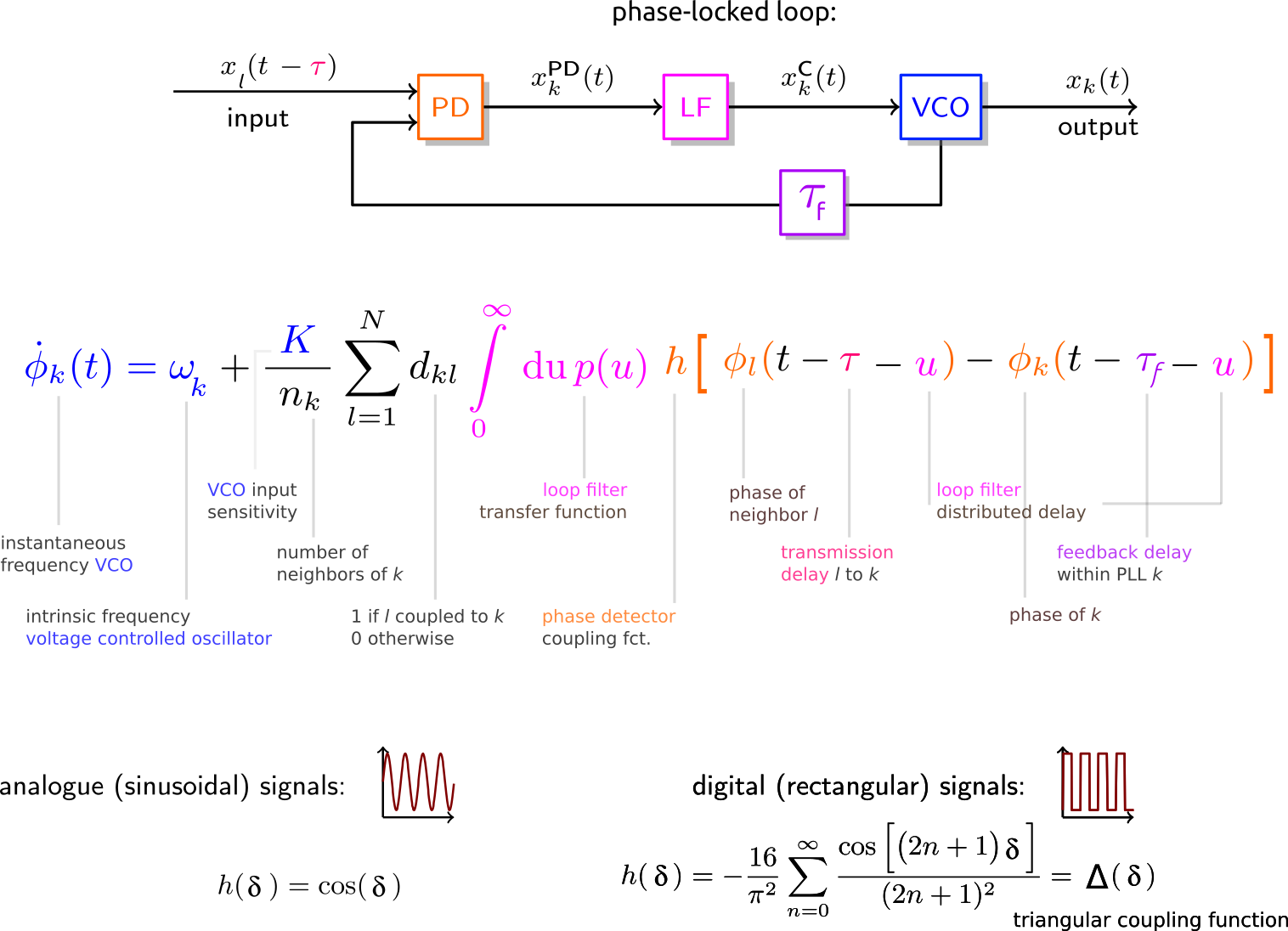
In this project we derived a mathematical model that is independent of the details of the circuitry of phase-locked loop (PLL) clocks. These consist of three main components, the phase-detector (PD), the loop filter (LF) and the voltage-controlled oscillator (VCO) and a signal path that feeds the output signal back to input. We start with generic periodic VCO output signals for which we assume constant amplitudes. These are exchanged between the PLLs. In each PLL, the PD detects the low and hight frequency components of the combined feedback and external input signals. Subsequently we assume, that the LF filters the high-frequency components ideally, which yields the control signal that affects the instantaneous frequency of the VCO. Under these assumptions we obtain a phase-model description of the dynamics of the instantaneous frequencies in PLL networks.
Schematic of a PLL and phase-model for a network of mutually delay-coupled PLLs.
For a Dirac-delta impulse response of the LF and no feedback and transmission delay, this reduces to the well known Kuramoto model of coupled phase-oscillators.
Synchronized solutions
From this model we can calculate the frequencies and phase relations between all oscillators in a network. In the case of identical clock elements the frequencies of synchronized states depend on the intrinsic frequencies of the individual clocks, the coupling strength, the feedback and transmission delays and the coupling function. There are also states with constant non-zero phase differences between the clocks, which are called -twist or splay states.
Linear stability
Whether these synchronized states are stable, marginally stable or unstable can be determined by performing a linear stability analysis. This requires the information about the network topology, i.e., which PLLs are coupled, the internal parameters of the clock elements and the transmission delays.
Experimental setup and results
We validated our theoretical predictions that were obtained using the phase model by carrying out experiments in prototype PLL networks. These consisted of low cost self-soldered PLLs prototypes running at kHz.
Using a microcontroller to artificially delay the coupling between PLLs at 1kHz
In order to measure the effects of transmission delay with clock elements running at just kHz, delay-times should be of the order of milliseconds and at least s. Instead of using hundreds of kilometers of copper wiring, we use a micro-controller that buffers the states and histories of the PLLs and then sends these signals at specified delays to the respective coupled nodes in the clock network.
Sketch of experimental setup of mutually delay-coupled DPLLs.
The experimental results confirm qualitatively and quantitatively the theoretical model predictions and can be found in the links to the published work at the beginning of this blog entry. In those publications we present results for networks of mutually delay-coupled DPLL networks that range from two to nine clock elements in different coupling topologies, such as ring, chain and square lattice with nearest neighbor interactions with open and closed boundary conditions.
Matlab Simulink, LTSpice and VHDL based simulations
In addition we performed numerical simulations of the dynamics of such PLL networks in python, Matlab/Simulink and LTSpice and VHDL. The Matlab/Simulink simulations test the assumption of the ideal filtering of the high frequency components from the phase detection. The python code allows to simulate large networks of delay-coupled PLL networks in many different settings, heterogeneous parameters and with noise. The LTSpice simulations on the level of the circuitry, i.e., voltages and currents in such systems, help us to plan the next versions of experimental setups and applications.
The next generation experimental setup with tunable devices and running at 1-10 MHz
Currently we are working on the next generation of prototype PLL elements running in the MHz frequency regime. This setup will allow to tune many parameters of the individual clock components, such as the delay-times, the cut-off frequencies of the LFs, the coupling strengths and the feedback path inverter elements. It will provide the necessary means to quantify the effects of noise in such systems.
THE P in PVT variations — Networks of Heterogeneous Phase-locked loops
The production process of CMOS integrated electronic circuitry yields highly heterogeneous elements. This leads to static, process induced heterogeneity. It can not be assumed that these heterogeneities can be characterized through measurements for mass market units. Hence, electronic architectures based such elements need to perform their tasks robustly in the presence of large differences in the parameters of the different nodes and network. Since self-organized dynamics in large complex systems depends on many parameters we study the effects of such static heterogeneities for CMOS based clocking networks.
This work, that has mainly been carried out together with Nirmal Punetha, produced some exiting results that we will soon publish in a peer-reviewed scientific journal. A more detailed blog entry that highlights the most important and exiting results will follow soon.
Beyond linear Stability — The basins of Attraction of synchronized states
Another important part of our efforts is the characterization of the basins of attractions of self-organized synchronized states. This goes beyond linear stability analysis which can only provide information about a systems reaction to small perturbations from its possible states.
We approach this question using the -adaption algorithm develop by the group of Prof. Dr. Ivo Sbalzarini. Instead of performing brute-force sampling of highly dimensional spaces of phase configurations for large systems of coupled elements, we make use of volume approximation to learn about the sizes of the basins of attraction for different synchronized states. This enables us to plan networks for technical applications, for which it is necessary to provide the conditions for which robust functionality can be guaranteed.
This will also be presented in more detail in a separate blog post.
Noisy Phase-locked Loops
Langevin-equations for delay-coupled phase-locked loops
 fF.
fF.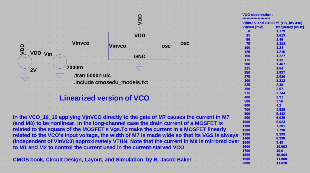
 .
.
 -twist or splay states.
 kHz.
kHz.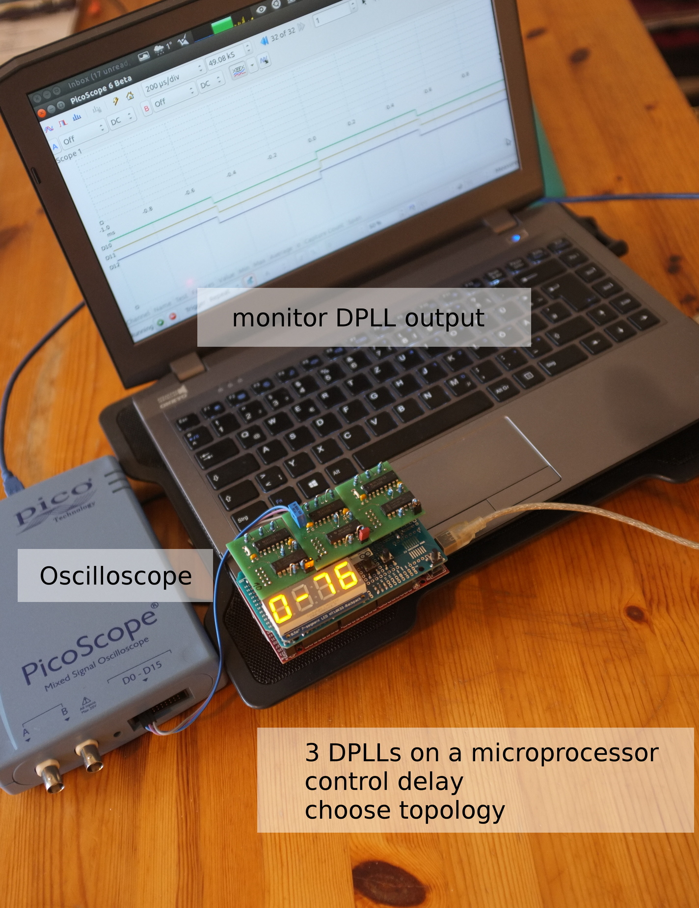
 s. Instead of using hundreds of kilometers of copper wiring, we use a micro-controller that buffers the states and histories of the PLLs and then sends these signals at specified delays to the respective coupled nodes in the clock network.
 square lattice with nearest neighbor interactions with open and closed boundary conditions.
 -adaption